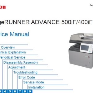
Description
SERVICE MANUAL TABLE OF CONTENTS
Safety Precautions
Laser Safety
How to Handle the Laser Scanner Unit
Toner Safety
Notes When Handling a Lithium Battery
Notes on Assembly/Disassembly
1. Product Overview
Product Lineups
Product Features
Specifications
Name of Parts
2. Technical Explanation
Basic Configuration
Document Exposure/Feeder System
Controller System
Laser Control System
Image Formation System
Fixing System
Pickup / Feed System
External Auxiliary System
Embedded RDS
Setting Information Export/Import Function (DCM)
3. Periodical Service
Periodically Replaced Parts
Durable Parts
Periodical Services
Cleaning
4. Disassembly/Assembly
List of Parts
External Cover, Internal Cover
External Cover, Internal Cover Disassembly/Assembly Procedure
Document Exposure, Feed System
Document Exposure, Feed System Disassembly/Assembly Procedure
Controller System
Controller System Disassembly/Assembly Procedure
Laser Exposure System
Laser Exposure System Disassembly/Assembly Procedure
Image Formation System
Image Formation System Disassembly/Assembly Procedure
Fixing System
Fixing System Disassembly/Assembly Procedure
Pickup Feeder System
Pickup Feeder System Disassembly/Assembly Procedure
5. Adjustment
Overview
Adjustment at Parts Replacement
6. Troubleshooting
Test Print
Trouble shooting items
Version Upgrade
Debug Log
7. Error/Jam/Alarm
Outline.
Error Codes
Jam Code
Alarm Code
8. Service Mode
Overview
COPIER
FEEDER
FAX
TESTMODE
9. Installation
Copy Card Reader-F1
Installation Procedure
MiCARD Attachment Kit-B1
Installation Procedure
Copy Control Interface Kit-C1
Installation Procedure
APPENDICES
Service Tools
General Circuit Diagram
Print Sequence
Backup Data
Soft Counter Specifications
Safety Precautions
Laser Safety
How to Handle the Laser Scanner Unit
Toner Safety
Notes When Handling a Lithium Battery
Notes on Assembly/Disassembly
PARTS MANUAL TABLE OF CONTENTS
Figure A1 ASSEMBLY LOCATION DIAGRAM
Figure A2 OPTION PARTS CATALOG LIST
Figure 001D ACCESSORIES(EXCEPT FAX model)
Figure 001E ACCESSORIES(FAX model)
Figure 100D EXTERNAL COVERS, PANELS, ETC.(EXCEPT FAX model)
Figure 100E EXTERNAL COVERS, PANELS, ETC.(FAX model)
Figure 101 INTERNAL COMPONENTS 1
Figure 102 INTERNAL COMPONENTS 2
Figure 103 INTERNAL COMPONENTS 3
Figure 104C INTERNAL COMPONENTS 4(230V)
Figure 105 INTERNAL COMPONENTS 5
Figure 106 INTERNAL COMPONENTS 6
Figure 107E INTERNAL COMPONENTS 7(EXCEPT FAX model)
Figure 107F INTERNAL COMPONENTS 7(FAX model MF728Cdw
Figure 107G INTERNAL COMPONENTS 7(FAX model MF729Cx)
Figure 130E CONTROL PANEL ASS’Y(i-SENSYS MF724Cdw)
Figure 130G CONTROL PANEL ASS’Y(i-SENSYS MF729Cx)
Figure 130G CONTROL PANEL ASS’Y(i-SENSYS MF729Cx)
Figure 160C READER/ADF ASSEMBLY
Figure 165 PAPER FEEDER ASSEMBLY
Figure 300 CASSETTE
Figure 400 READER ASSEMBLY
Figure 460 LASER SCANNER ASS’Y
Figure 530 INTERMEDIATE TRANS. BELT ASS’Y
Figure 810C FIXING ASS’Y
Figure 900C MAIN CONTROLLER PCB ASSEMBLY (MF729Cdw,MF729Cx)
Figure 900D MAIN CONTROLLER PCB ASSEMBLY (MF724Cdw)
Figure 900E MAIN CONTROLLER PCB ASSEMBLY (MF728Cdw)
Figure ZZA MECHANICAL STANDARD PARTS (HOW TO USE)
Figure ZZB ( 1 / 7 ) MECHANICAL STANDARD PARTS (SCREWS)
Figure ZZB ( 2 / 7 ) MECHANICAL STANDARD PARTS (SCREWS)
Figure ZZB ( 3 / 7 ) MECHANICAL STANDARD PARTS (SCREWS)
Figure ZZB ( 4 / 7 ) MECHANICAL STANDARD PARTS (SCREWS)
Figure ZZB ( 5 / 7 ) MECHANICAL STANDARD PARTS (SCREWS)
Figure ZZB ( 6 / 7 ) MECHANICAL STANDARD PARTS (SCREWS)
Figure ZZB ( 7 / 7 ) MECHANICAL STANDARD PARTS (SCREWS)
Figure ZZC MECHANICAL STANDARD PARTS (BOLTS)
Figure ZZD MECHANICAL STANDARD PARTS (NUTS)
Figure ZZE ( 1 / 3 ) MECHANICAL STANDARD PARTS (RETAINING RINGS)
Figure ZZE ( 2 / 3 ) MECHANICAL STANDARD PARTS (RETAINING RINGS)
Figure ZZE ( 3 / 3 ) MECHANICAL STANDARD PARTS (RETAINING RINGS)

