Description
SERVICE MANUAL TABLE OF CONTENTS
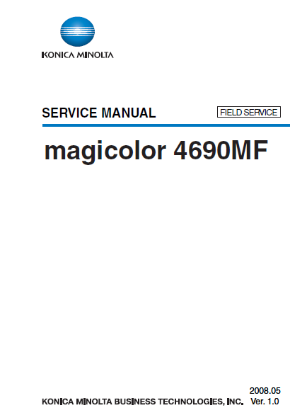
magicolor 4690MF Main body
Outline
1. System configuration
2. Product specifications
2.1 Fax specifications
Maintenance
3. Periodical check
3.1 Maintenance items
3.2 Maintenance parts
3.3 Concept of parts life
3.4 Maintenance procedure (Periodical check parts)
4. Service tool
4.1 Service material list
4.2 CE Tool list
4.3 Consumable parts
5. Remote Setup Utility
5.1 About RSU
5.2 Outline
5.3 Connection methods
5.4 Setup
5.5 Operation
5.6 Function setting
5.7 Troubleshooting
6. Firmware upgrade
6.1 Controller firmware upgrading
7. Other
7.1 Disassembly/Adjustment prohibited items
7.2 Disassembly/Assembly/Cleaning list (Other parts)
7.3 Disassembly/Assembly procedure
7.4 Cleaning procedure
Adjustment/Setting
8. How to use the adjustment section
9. Description of the control panel
9.1 Control panel display
10. REPORT/STATUS mode
10.1 REPORT/STATUS mode function tree
10.2 TOTAL PRINT
10.3 SUPPLY STATUS
10.4 TX/RX RESULT
10.5 REPORT
11. Utility Mode
11.1 Utility Mode function tree
11.2 MACHINE SETTING
11.3 PAPER SETUP
11.4 ADMIN MANAGEMENT
11.5 COPY SETTING
11.6 DIAL REGISTER
11.7 FAX TX OPERATION
11.8 FAX RX OPERATION
11.9 REPORTING
11.10 SCAN SETTING
12. User Service Mode
12.1 User Service Mode function tree
12.2 FAX MAINTENANCE
12.3 ADJUST
12.4 AIDC MODE
12.5 CRU USAGE
12.6 SUPPLIES REPLACE
13. SERVICE MODE
13.1 SERVICE MODE entry procedure
13.2 SERVICE MODE function tree
13.3 SERVICE’S CHOICE
13.4 ADJUST
13.5 COUNTER
13.6 DISPLAY
13.7 FUNCTION
13.8 SOFT SWITCH
13.9 REPORT
13.10 ADMIN REGISTRATION
13.11 FIXED ZOOM CHANGE
13.12 FACTORY TEST
13.13 CLEAR DATA
14. SOFT SWITCH set
14.1 Description
14.2 Default Setting
14.3 Soft switch definition
15. Fax Protocols
15.1 G3 ECM (G3 Error Correction Mode)
15.2 Line Control
15.3 Table of reference code
15.4 How to analyze the T30 protocol monitor
Troubleshooting
16. Jam Display
16.1 Misfeed Display
16.2 Sensor layout
16.3 Solution
17. Malfunction code
17.1 Trouble codes (service call)
17.2 Resetting a malfunction
17.3 Solution
18. Power supply troubles
18.1 Machine is not Energized at All (PU1 Operation Check)
18.2 Control panel indicators do not light
18.3 Fusing Heaters do not Operate
19. Image quality problems
19.1 Printer system
20. FAX error
20.1 Communication error
20.2 Outline
20.3 Error occurring during transmission
20.4 Error code
Appendix
21. Parts layout drawing
21.1 Main body
21.2 Auto Document Feeder Unit
21.3 Lower feeder unit (option)
22. Connector layout drawing
AUTOMATIC DOCUMENT FEEDER
Outline
1. Product specifications
Maintenance
2. Periodical check
2.1 Maintenance procedure (Periodical check parts)
3. Other
3.1 Disassembly/Adjustment prohibited items
3.2 Disassembly/Assembly list (Other parts)
3.3 Disassembly/Assembly procedure
3.4 Cleaning Procedure
Adjustment/Setting
4. How to use the adjustment section
5. SERVICE MODE
5.1 SERVICE MODE entry procedure
5.2 ADJUST
Troubleshooting
6. Jam Display
6.1 Misfeed display
6.2 Sensor layout
6.3 Solution
LOWER FEEDER UNIT
Outline
1. Product specifications
Maintenance
2. Periodical check
2.1 Maintenance procedure (periodic parts check)
3. Other
3.1 Disassembly/adjustment prohibited items
3.2 Disassembly/Assembly list (Other parts)
3.3 Disassembly/Assembly procedure
3.4 Cleaning Procedure
Adjustment/Setting
4. How to use the adjustment section
5. Mechanical adjustment
Troubleshooting
6. Jam Display
6.1 Misfeed display
6.2 Misfeed display resetting procedure
6.3 Sensor layout
6.3 Solution
PARTS MANUAL TABLE OF CONTENTS
1 EXTERNAL PARTS
2 IR SECTION
3 MAIN FRAME SECTION
4 T/C RAIL SECTION
5 I/U CONTACT SECTION
6 I/U RAIL SECTION
7 WASTE TONER TRANSPORT SECTION
8 TRANSFER BELT UNIT
9 PRINT HEAD SECTION
10 CASSETTE SECTION
11 VERTICAL CONVEYANCE SECTION
12 SWITCH BACK SECTION
13 HORIZONTAL TRANSPORT UNIT
14 FUSING SECTION
15 TRANSFER PRESSURE DRIVE SECTION
16 HOPPER DRIVE SECTION
17 MAIN DRIVE SECTION
18 ELECTRICAL COMPONENTS
19 ADF UNIT
20 ADF TRANSPORT SECTION
21 ADF TRAY SECTION
22 ADF FRAME SECTION
23 WIRING
24 WIRING ACCESSORIES AND JIGS
25 ACCESSORY PARTS

