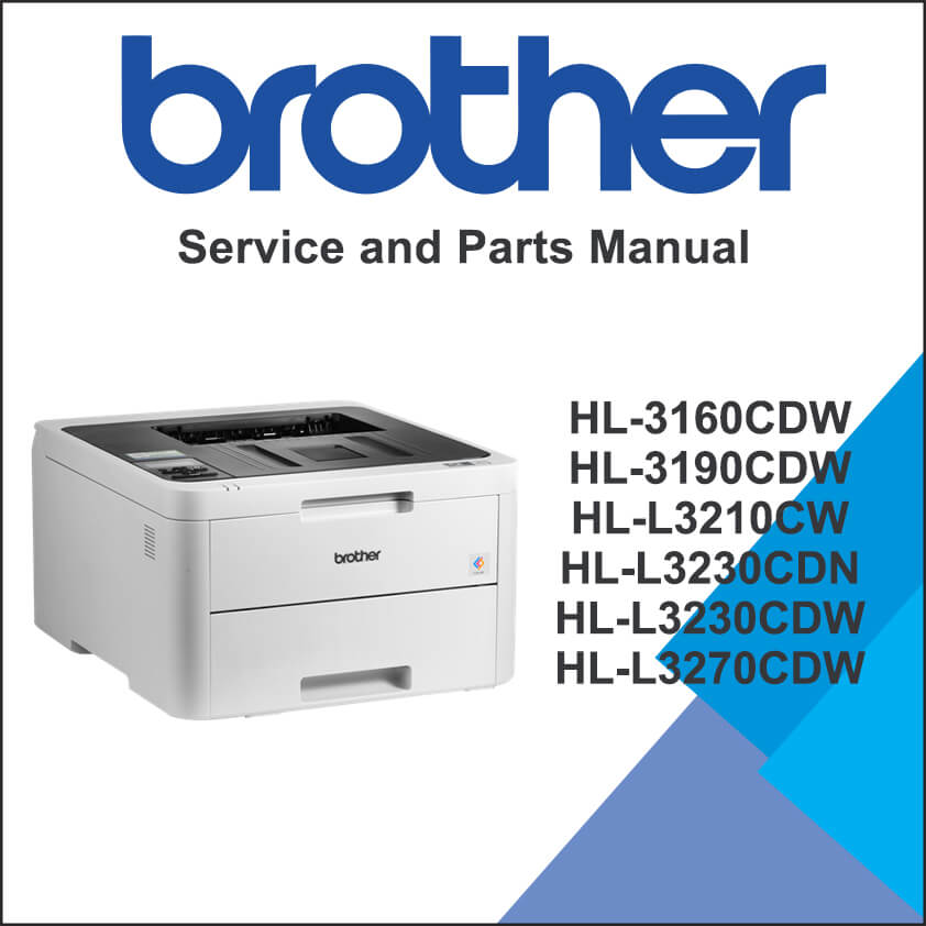
SERVICE MANUAL TABLE OF CONTENTS
SAFETY INFORMATION
CHAPTER 1 SUPPLEMENTAL SPECIFICATIONS
1. GENERAL
2. NETWORK CONNECTIVITY
3. SERVICE INFORMATION
4. SUPPLIES
CHAPTER 2 ERROR INDICATION AND TROUBLESHOOTING
1. INTRODUCTION
1.1 Precautions
1.2 Checks before Commencing Troubleshooting
2. OVERVIEW
2.1 Cross-section Drawing
2.2 Paper Feeding
2.3 Operation of Each Part and Location of Parts
2.4 Block Diagram
2.5 Main Components
3. ERROR INDICATIONS
3.1 Error Codes
3.2 Error Message
4. TROUBLESHOOTING
4.1 Error Cause and Remedy
4.2 Troubleshooting for Paper Feeding Problems
4.3 Troubleshooting for Image Defects
4.4 Troubleshooting for Software Problems
4.5 Troubleshooting for Network Problems
4.6 Troubleshooting for Control Panel Problems
4.7 Troubleshooting for Toner Cartridge and Drum Unit Problems
4.8 Troubleshooting for Fuser Unit Problems
4.9 Troubleshooting for LED ASSY Problems
4.10 Troubleshooting for PCB Problems
4.11 Troubleshooting for Other Problems
CHAPTER 3 DISASSEMBLY/REASSEMBLY
1. SAFETY PRECAUTIONS
2. PACKING
3. SCREW CATALOGUE
4. SCREW TORQUE LIST
5. LUBRICATION
6. OVERVIEW OF GEARS
7. HARNESS ROUTING
8. DISASSEMBLY FLOW
9. DISASSEMBLY PROCEDURE
9.1 Preparation
9.2 Paper tray / T1 separation pad ASSY
9.3 Back cover
9.4 Rear flapper sub ASSY
9.5 Fuser cover ASSY / Fuser unit
9.6 Side cover L
9.7 Side cover R
9.8 Back cover lower
9.9 Top cover ASSY
9.10 LCD panel ASSY
9.11 LED control flat cable / LED control PCB
9.12 LED ASSY (Y/M/C/K) / LED ASSY flat cable (Y/M/C/K)
9.13 High-voltage power supply PCB / Develop release sensor PCB
9.14 Fan
9.15 WLAN PCB
9.16 Main PCB
9.17 Cartridge sensor relay flat cable
9.18 Develop release clutch / Process drive unit / High-voltage power supply flat cable / Process motor flat cable / Paper feed motor flat cable
9.19 T1 pick-up clutch / Registration clutch / Paper feed drive unit
9.20 Eject sensor PCB
9.21 Manual feed cover ASSY
9.22 Roller holder ASSY
9.23 Paper feed unit
9.24 Paper eject ASSY
9.25 Duplex tray
9.26 Low-voltage power supply PCB
9.27 Registration mark sensor L PCB / Registration mark sensor R PCB
CHAPTER 4 ADJUSTMENTS AND UPDATING OF SETTINGS REQUIRED AFTER PARTS REPLACEMENT
1. IF YOU REPLACE THE MAIN PCB
1.1 Configure for Country/Region and Model (Function code 74)
1.2 Installing the Firmware (Sub Firmware and Main Firmware)
1.3 Initializing the EEPROM of the Main PCB (Function code 01)
1.4 Adjusting Touch Panel (Function code 61) (Touch panel models only)
1.5 Continuous Adjustments of Density and Registration Sensor (Function code 73)
1.6 Setting the Serial Number (Function code 80)
2. IF YOU REPLACE THE REGISTRATION MARK SENSOR ASSY OR LED ASSY
2.1 Continuous Adjustments of Density and Registration Sensor (Function code 73)
3. IF YOU REPLACE THE LOW-VOLTAGE POWER SUPPLY PCB
3.1 Resetting Irregular Power Supply Counter of the Low-voltage Power Supply PCB (Reset counters for consumable parts (Function code 88))
4. IF YOU REPLACE THE TOP COVER ASSY, LCD, LCD PANEL ASSY OR PANEL PCB
4.1 Adjusting Touch Panel (Function code 61) (Touch panel models only)
4.2 Checking LCD Operation (Function code 12)
5. IF YOU REPLACE THE FUSER UNIT
5.1 Resetting Printed Pages Counter of the Fuser Unit(Reset counters for consumable parts (Function code 88))
6. IF YOU REPLACE A PF KIT
6.1 Resetting Printed Pages Counter of a PF Kit (Reset counters for consumable parts (Function code 88))
CHAPTER 5 SERVICE FUNCTIONS
1. MAINTENANCE MODE
1.1 How to Enter Maintenance Mode
1.2 List of Maintenance Mode Functions
1.3 Details of Maintenance Mode Functions
CHAPTER 6 WIRING DIAGRAM
1. WIRING DIAGRAM
CHAPTER 7 PERIODICAL MAINTENANCE
1. PRECAUTIONS
2. PERIODICAL REPLACEMENT PARTS
2.1 Preparation
2.2 Fuser unit
2.3 PF kit 1
APPENDIX 1 SERIAL NUMBERING SYSTEM
APPENDIX 2 DELETING USER SETTING INFORMATION
APPENDIX 3 INSTALLING THE MAINTENANCE PRINTER DRIVER
PARTS MANUAL TABLE OF CONTENTS
1. FRAME
2. PAPER FEED DRIVE
3. PROCESS DRIVE
4. LED TOP COVER
5. PAPER FEEDER
6. DX
7. PAPER CASSETTE
8. FUSER UNIT
9. PAPER EJECT
10. COVERS & LABEL
11. PCB
12. OPTION
13. PACKAGING

