Description
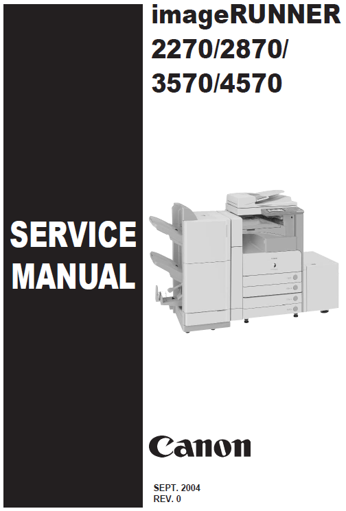
Service Manual Table of Contents
Chapter 1 Introduction
1.1 Product Specifications
1.1.1 Safety
Chapter 2 Installation
2.1 Unpacking and Installation
2.1.1 Connecting the Cable
2.2 Installing the Reader Heater
2.2.1 Checking the Parts
2.2.2 Turning Off the Host Machine
2.2.3 Installation Procedure
2.3 Installing the Cassette Heater for the Cassette Pedestal
2.3.1 Checking the Contents
2.3.2 Checking the Contents
2.3.3 Checking the Contents
2.3.4 Turning Off the Host Machine
2.3.5 Installation Procedure (Cassette Heater Unit 29)
2.3.6 Installation Procedure (Cassette Heater AttachmentD2)
2.3.7 Installation Procedure (Cassette Heater Unit36)
2.4 Installing the Deck Heater
2.4.1 Checking the Parts to Install
2.4.2 Turning Off the Host Machine
2.4.3 Installation Procedure
2.5 Installing the Voice Guidance Kit
2.5.1 A point to keep in mind at installation
2.5.2 Checking the Contents
2.5.3 Turning Off the Host Machine
2.5.4 Installation Procedure
2.6 Installing the Voice Operation Kit
2.6.1 A point to keep in mind at installation
2.6.2 Checking the Contents
2.6.3 Turning Off the Host Machine
2.6.4 Installation Procedure
Chapter 3 Main Controller
3.1 Construction
3.1.1 Construction and Mechanisms
3.2 Construction of the Electrical Circuitry
3.2.1 Main Controller PCB
3.2.2 HDD
3.3 Start-Up Sequence
3.3.1 Overview
3.3.2 Start-Up Sequence
3.4 Shut-Down Sequence
3.4.1 Overview
3.4.2 Flow of Operation
3.5 Image Processing
3.5.1 Overview of the Image Flow
3.5.2 Construction of the Image Processing Module
3.5.3 Reader Unit Input Image Processing
3.5.4 Compressio/ Extesion/ Editing Block
3.5.5 Printer unit Output Image Processing
3.6 Flow of Image Data
3.6.1 Flow of Image Data According to Copy Functions
3.6.2 Flow of Image Data for the Box Function
3.6.3 Flow of Image Data for the SEND Function
3.6.4 Flow of Image Data for the Fax Transmission
3.6.5 Flow of Image Data for the Fax Reception Function
3.6.6 Flow of Image Data for the PDL Function
3.7 Parts Replacement Procedure
3.7.1 Main Controller PCB
3.7.2 SDRAM
3.7.3 Boot ROM
3.7.4 HDD
Chapter 4 Laser Exposure
4.1 Construction
4.1.1 Specifications, Control Mechanism, and Functions
4.1.2 Major Components
4.1.3 Construction of the Control System
4.2 Basic Sequence
4.2.1 Basic Sequence
4.3 Various Controls
4.3.1 Controlling the Laser Activation Timing
4.3.2 Controlling the Intensity of Laser Light
4.3.3 Controlling the Laser Scanner Motor
4.3.4 Controlling the Laser Shutter
4.4 Parts Replacement Procedure
4.4.1 Laser Scanner Unit
Chapter 5 Image Formation
5.1 Construction
5.1.1 Specifications of the Image Formation System
5.1.2 Major Components of the Image Formation System
5.2 Image Formation Process
5.2.1 Image Formation Process (outline)
5.2.2 Image Formation Process (image formation)
5.3 Basic Sequence
5.3.1 Sequence of Operation (initial rotation)
5.3.2 Sequence of Operation (copying)
5.3.3 Sequence of Operation (last rotation)
5.4 Image Stabilization Control
5.4.1 Overview
5.4.2 APVC Control
5.4.3 ATVC Control
5.5 Drum Unit
5.5.1 Charging Mechanism
5.6 Drum Cleaner Unit
5.6.1 Photosensitive Drum Cleaning
5.7 Developing Unit
5.7.1 Controlling the Developing Bias
5.8 Toner Container
5.8.1 Overview
5.8.2 Route of Toner Supply
5.8.3 Controlling the Drive of the Toner Cartridge
5.8.4 Toner Supply Control
5.8.5 Recovery Sequence
5.8.6 Toner Level Detection
5.9 Transfer Unit
5.9.1 Outline of the Transfer Unit
5.9.2 Controlling the Transfer Bias
5.9.3 Cleaning
5.9.4 Separation Mechanism
5.10 Transfer Mechanism
5.10.1 Transfer Guide Bias
5.11 Photosensitive Drum Cleaning
5.11.1 Outline
5.11.2 Collection of Waste Toner
5.11.3 Checking the Waste Toner Box
5.12 Parts Replacement Procedure
5.12.1 Pre-Exposure Lamp
5.12.2 Drum Unit
5.12.3 Hopper Assembly
5.12.4 Sub Hopper
5.12.5 Developing Assembly
5.12.6 Developing Cylinder
5.12.7 Transfer Charging Roller
5.12.8 Waste Toner Box
5.12.9 Toner Level Sensor
5.12.10 Toner Feedscrew Motor
5.12.11 Static Charge Eliminator
Chapter 6 Pickup/Feeding System
6.1 Construction
6.1.1 Specifications, Controls, and Functions
6.1.2 Division into Blocks
6.1.3 Arrangement of Rollers
6.1.4 Diagram of Paper Paths (printer on its own)
6.1.5 Diagram of Paper Paths (w/ 3 Way Unit-A1 /copy tray)
6.1.6 Diagram of Paper Paths (w/ Finisher-S1/copy tray)
6.1.7 Diagram of Paper Paths (w/ Finisher-Q3/Saddle Finisher-Q4)
6.1.8 Arrangement of Sensors
6.1.9 Route of Drive
6.2 Basic Sequence
6.2.1 Basic Sequence
6.2.2 Increase in Speed
6.3 Detecting Jams
6.3.1 Delay Jams
6.3.2 Stationary Jams
6.3.3 Other Jams
6.4 Cassette Pick-Up Unit
6.4.1 Overview
6.4.2 Basic Sequence
6.4.3 Identifying the Paper Size
6.4.4 Setting Up the Universal Cassette
6.4.5 Paper Level Sensor
6.5 Manual Feed Pickup Unit
6.5.1 Overview
6.5.2 Basic Sequence of Operation
6.5.3 Identifying the Paper Size
6.5.4 Paper Retaining Mechanism
6.6 Registration Unit
6.6.1 Overview
6.6.2 Checking Horizontal Registration
6.7 Duplex Feeding Unit
6.7.1 Overview
6.7.2 Sequence of Image Formation
6.7.3 Flow of Paper (w/o/ delivery option)
6.7.4 Flow of Paper (w/ delivery option)
6.8 Parts Replacement Procedure
6.8.1 Pick-up Unit 1
6.8.2 Pick-up Unit 2
6.8.3 Pickup Roller
6.8.4 Sensor Mount
6.8.5 Cassette Pick-up Motor 1
6.8.6 Cassette Pick-up Motor 2
6.8.7 Cassette Size Sensor
6.8.8 Cassette Retry Paper Sensor
6.8.9 Cassette Paper Sensor
6.8.10 Cassette Paper Level Sensor (A/B)
6.8.11 Slide Resistor
6.8.12 Cassette Pickup Solenoid
6.8.13 Cassette Size Sensor Relay PCB
6.8.14 Manual Tray Assembly
6.8.15 Manual Feed Unit
6.8.16 Manual Pickup Roller
6.8.17 Manual Pick-up Clutch
6.8.18 Manual Separation Pad
6.8.19 Registration Clutch
6.8.20 Feeding Roller
6.8.21 Vertical Path Roller
6.8.22 Duplex Feed Roller 2
6.8.23 Duplex Feed Sensor
6.8.24 Delivery Assembly 1
6.8.25 Fixing/ Delivery Drive Assembly
6.8.26 Separation Roller
Chapter 7 Fixing System
7.1 Construction
7.1.1 Specifications, Control Mechanisms, and Functions
7.1.2 Major Components
7.2 Basic Sequence
7.2.1 Power-On Sequence
7.2.2 Down Sequence
7.3 Various Control Mechanisms
7.3.1 Controlling the Speed of the Fixing Film
7.3.2 Controlling the Fixing Film Temperature
7.3.3 Cleaning
7.3.4 Detecting the Passage of Paper
7.4 Protective Functions
7.4.1 Protective Functions
7.4.2 Detecting an Error
7.5 Parts Replacement Procedure
7.5.1 Fixing Unit
7.5.2 Pressure Roller
7.5.3 Cleaning Roller
7.5.4 Fixing Film
7.5.5 Internal Delivery Sensor
7.5.6 Fixing Film Sensor
Chapter 8 External and Controls
8.1 Parts Replacement Procedure
8.1.1 Main Drive Assembly
8.1.2 Power Supply Unit
8.1.3 Control Panel
8.1.4 Control Panel LCD Unit
8.1.5 DC Controller PCB
8.1.6 Control Panel Inverter PCB
8.1.7 Control Panel Key Switch PCB
8.1.8 Control Panel CPU PCB
8.1.9 All Night Power Supply PCB
8.1.10 Controller Power Supply PCB
8.1.11 Option Power Supply PCB
8.1.12 High-Voltage PCB
8.1.13 Exhaust Fan
8.1.14 Motor of Main Drive Assembly
8.1.15 Fixing Driver Motor
8.1.16 Right Door
8.1.17 Circuit Braker
Chapter 9 Correcting Faulty Images
9.1 Troubleshooting
9.1.1 Image Faults
9.1.2 Faulty Feeding
9.1.3 Malfunction
9.1.4 Network
9.1.5 Transmission/fax-related
9.1.6 Jam (Main Unit)
9.1.7 Error Code
9.1.8 FAX ## Code
9.1.9 Specifications-related FAQ
Parts Manual Table of Contents


